

Technical Support
Clean room application
1.Clean Room / Aseptic Clean Room
Clean Room is a room in which the concentration of airborne particles is controlled, and which is constructed and used in a manner to minimize the introduction, generation, and retention of particles inside the room, and in which other relevant parameters, e.g. temperature, humidity, and pressure, are controlled as necessary. Also, the illumination, hazardous steam, and airflow direction and its velocity are also defined.
Aseptic Clean Room is a room where the Microorganisms such as bacteria or virus and biological particles are more strictly controlled.
Industrial Clean Room ICR
It is the Clean Room for industrial use, such as Precision industries, electric industries, etc.
Biological Clean Room BCR
It is the aseptic Clean Room for biological medicine or laboratories. Most of the bacteria or virus are attached to the airborne particles, which can be filtered with Filter System. However, finer bacteria can be sterilized by ultra-violet ray lamp or Hydrogen Peroxide Gas.
2.Features for Clean Room Air-conditioning
I.Temperature and humidity requirements are higher than general air-con.
The temperature requirement for general air-con is between 18°C and 26°C and the relative humidity is between 40% and 65%; while the temperature in Clean Room should be controlled between 22°C and 24°C and the humidity in it should be between 45% and 55%.
II.Constant temperature and humidity control
It is extremely temperature-sensitive for the semiconductor industry; therefore, the temperature and humidity should be controlled within ± 1°C and ± 3% in most of the Clean Room areas.
III.More air needed to balance the air pressure in Clean Room
A large amount of the chemicals and toxic gas will be required during the semiconductor production. Therefore, there will also be a huge amount of gas exhausted due to the volatile gas and exhaust gas. To maintain positive pressure inside the Clean Room, the air supply into the Clean Room is also relatively increased.
IV.Twenty-Four Seven running and monitoring on Air-con system
Part of the machines in the semiconductor production are highly sensitive to the temperature/humidity variation, such as the Stepper in Photo lithography area. A slight change of the temperature or humidity would affect the accuracy of the device. Moreover, the products like chips should be put in the environment with constant temperature and humidity. Therefore, the air-con system should be strictly monitored and managed.
V.Air pressure inside the Clean Room in the semiconductor factories
For the semiconductor factories, the air pressure in the Clean Room should be higher than the outside. Besides avoiding the influence from the temperature, humidity, and particles outside the Clean Room, it also helps extend the lifetime of the ULPA filter. However, the pressure difference should be constrained to avoid the cost increase from the increased out bounding air from Clean Room.
VI.Airflow direction
In order to remove the airborne particles inside the Clean Room, the air velocity shall reach the certain standard. Also, the airflow direction shall be controlled based on various levels of the Clean Room.
3.Clean Room System
The Clean Room system would produce clean air that is conformed to the specification. The clean air shall be steadily and continuously supplied to the FAB. Generally speaking, the source for producing clean air is called OUTSIDE AIR. It will undergo various of processing units in the Clean Room to produce the clean air that conforms to the specification. The following is the simplified process: The Outside air goes into the Make-up Air Unit (or MAU) to pre-filter the particle and control the temperature/humidity. After that, the air goes to the Mech. Chase. Inside the Chase, the circular air in the Clean Room and the supplying air from the MAU are mixed, and Dry Cooling Coil will cool down the air inside the Mech. Chase to the requested temperature by the Clean Room specification. Then the Fan Filter Unit (or FFU) enables the airflow cycle in the Clean Room to remove the particles and heat. Last, the air will be supplied to FAB area after filtered by the Ultra-low penetration air (or ULPA Filter).
4.Definition of Cleanliness
It means the capability for the Clean Room to effectively control the particle number in the specific room. To define the function of different types of the Clean Room, we define it based on the particles of “Specific Size” in “Specific Volume”.
Take the particle diameter above 0.5μm for example:
| Countryside | 10,000,000 – 50,000,000 particles/m3 | |
|---|---|---|
| City | 100,000,000 – 500,000,000 particles/m3 | |
| Indoors | 100,000,000 – 1,000,000,000 particles/m3 | |
| ISO Class 5 | control within 3,520 particles/m3 | |
| FS 209E Class 100 | control within 3,520 particles/m3 | |
5.Clean Room Classifications
| Industry | Cleanliness | |||||||||||
|---|---|---|---|---|---|---|---|---|---|---|---|---|
| ISO 2 | ISO 3 | ISO 4 | ISO 5 | ISO 6 | ISO 7 | ISO 8 | ||||||
| - | 209E Class 1 |
209E Class 10 |
209E Class 100 |
209E Class 1,000 |
209E Class 10,000 |
209E Class 100,000 |
||||||
| ICR | Semiconductor chip manufacturer | |||||||||||
| Semiconductor component supplier | Front end | |||||||||||
| Back end | ||||||||||||
| LCD Manufacturer | ||||||||||||
| Hard Disk manufacturer | ||||||||||||
| Precision industry manufacturer | ||||||||||||
| Mask manufacturer | ||||||||||||
| PCB manufacturer | ||||||||||||
| BCR | Pharmaceutical manufacturer | Filling area | ||||||||||
| Packing area | ||||||||||||
| Hospital | Aseptic therapy room | |||||||||||
| Aseptic operation room | ||||||||||||
| Food processing manufacturer | UHT milk | |||||||||||
| Fresh vegetables, fruits, boxed meal, bread | ||||||||||||
| Animal laboratory | Aseptic animal laboratory | |||||||||||
| SPF animal | ||||||||||||
Solutions
1.Electronics/Semiconductors
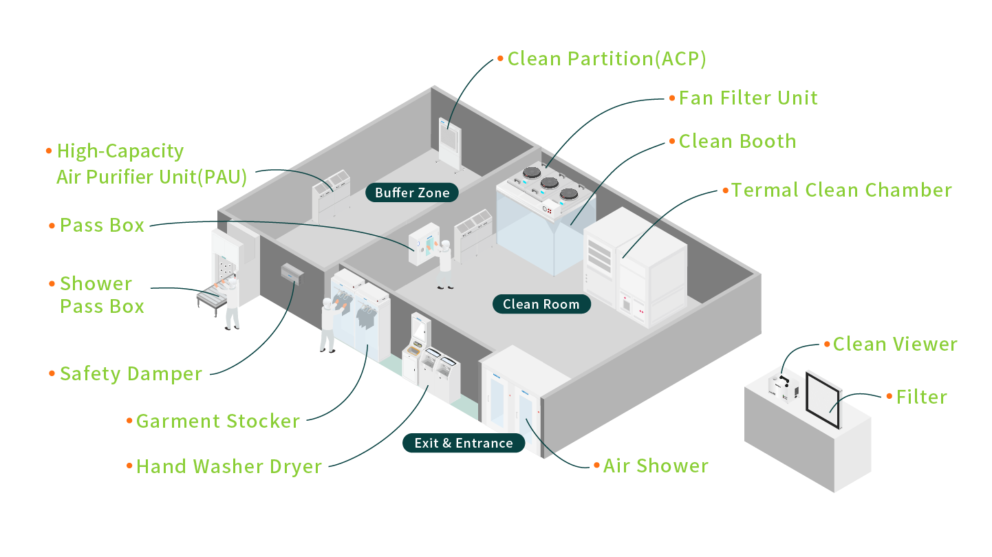
With increasing demands for quality and safety, the need for cleanroom technology continues to rise. The global cleanroom technology market is projected to grow from $9.37 billion in 2024 to $13.21 billion in 2029, demonstrating robust momentum.
Data indicates that semiconductor cleanrooms account for 61% of total cleanroom floor area, highlighting their critical role.The cleanroom environment is critical to semiconductor manufacturing, as the industry heavily relies on cleanroom technology to produce precision microelectronic components. Semiconductor chips are widely integrated into various electronic devices, including mobile phones, household appliances, automobiles, defense systems, and aerospace technologies. Moreover, with the rapid expansion of 5G networks, the proliferation of Internet of Things (IoT) devices, and the growing adoption of Artificial Intelligence (AI) and Machine Learning (ML) applications, the demand for semiconductors continues to rise, driving manufacturers to scale production capacities to meet market needs.
AIRTECH specializes in delivering high-performance, reliable cleanroom technology solutions tailored to the semiconductor industry. Our advanced systems are designed to enhance production efficiency while meeting stringent quality standards. We are committed to collaborating with our clients to facilitate the production of high-quality chips that cater to diverse industry applications, driving continuous progress in the technology sector.
- Cleanroom Fan Filter Unit(FFU)- Typically installed on cleanroom ceilings, this equipment purifies the air to effectively maintain the cleanliness of the indoor environment.
- Thermal Clean Chamber(TCC)- Certain semiconductor manufacturing processes are highly sensitive to fluctuations in temperature and humidity. Many products must also be stored in controlled environments with constant temperature and humidity, making precision climate control systems essential.
- Pressure Relief Damper(APD)- To prevent external contaminated air from entering the cleanroom, Pressure Relief Dampers (also known as pressure equalizers) are utilized to regulate and maintain a slight positive pressure within the room.
2.Clinics
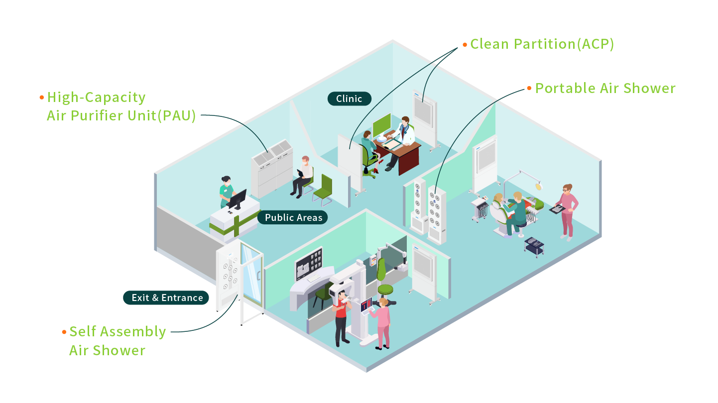
In the medical industry, the equipment in the diagnosis and treatment rooms requires a clean environment to prevent germs from affecting the health of patients and medical staff. Self Assembly Air Shower(AAS) can be set up from the beginning when people enter and exit, and high-volume air filters can also be placed in public areas. These equipment can quickly improve air quality and reduce the concentration of suspended particles.
In clinical settings, Partitioned Air Purifier (ACP) can be strategically placed to safeguard healthcare personnel and purify contaminated indoor air. Our systems incorporate large-area HEPA filters with an efficiency of 99.99% for particles as small as 0.3μm, effectively eliminating airborne bacteria and pathogens, preventing viral transmission, and reducing cross-contamination. These solutions create a safe treatment environment, offering patients enhanced peace of mind.
- High-Capacity Air Purifier Unit(PAU)- Featuring an oversized air outlet design, our systems rapidly improve air cleanliness in large spaces. They are ideal for offices, retail stores, clinics, schools, and other commercial facilities requiring High-Capacity Air Purifier Unit(PAU).
- Self Assembly Air Shower(AAS)- The Self Assembly Air Shower is our most efficient product, offering modular and highly adjustable configurations. The dimensions of the unit can be tailored to fit your specific spatial requirements, making it exceptionally suited for rapid deployment and installation.
- Partitioned Air Purifier(ACP)- The Partitioned Air Purifiers are easy to place and deliver robust performance in purifying contaminated indoor air. They effectively remove bacteria and pathogens from the air, preventing viral spread and cross-contamination, thereby enhancing safety for healthcare professionals and patients alike.
3.Food Industry
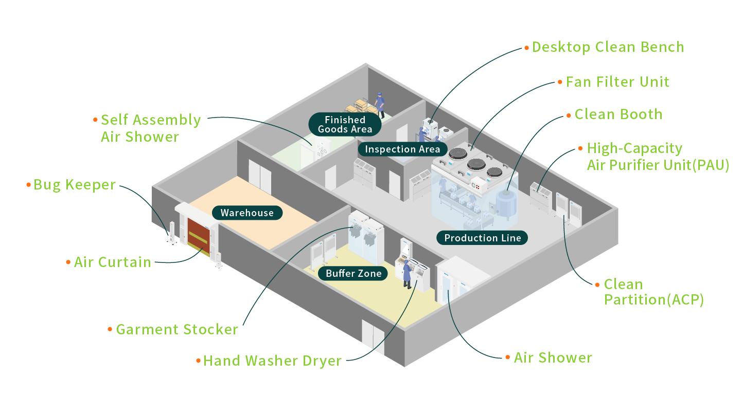
Food processing involves multiple stages, from raw material handling to packaging and distribution, with each step requiring strict compliance with hygiene and cleanliness standards.
Whether producing pastries, dairy products, or packaged beverages, our solutions enhance product hygiene and safety while helping enterprises meet international standards such as HACCP and ISO 22000, delivering higher-quality food experiences for consumers.
To meet the specific hygienic requirements and applications of various food industries, we offer specialized air curtains designed for cold storage facilities to prevent cold air leakage from storage areas. Additionally, our range of pest control equipment—including Insect-Proof Air Curtain, Commercial Insect Light Trap, and Door Type Insect Light Trap (Bug Shield) addresses contamination risks from pests at their source, reducing potential pollutants and ensuring operational integrity.
- Insect-Proof Air Curtain(AAC)- The air curtain forms a high-speed air barrier by blowing out the airflow of the turbulent flow system, which can effectively disrupt insects and prevent them from passing through. It can also reduce other small foreign objects and pollutants.
- Commercial Insect Light Trap(ABK)- Solve the problem of foreign matter mixing caused by insects in mosquito source areas, use insect traps to attract insects, and then use suction fans to capture invading insects. ※Our company's products all use physical trapping technology.
4.Pharmaceutical/Cosmetic Manufacturing
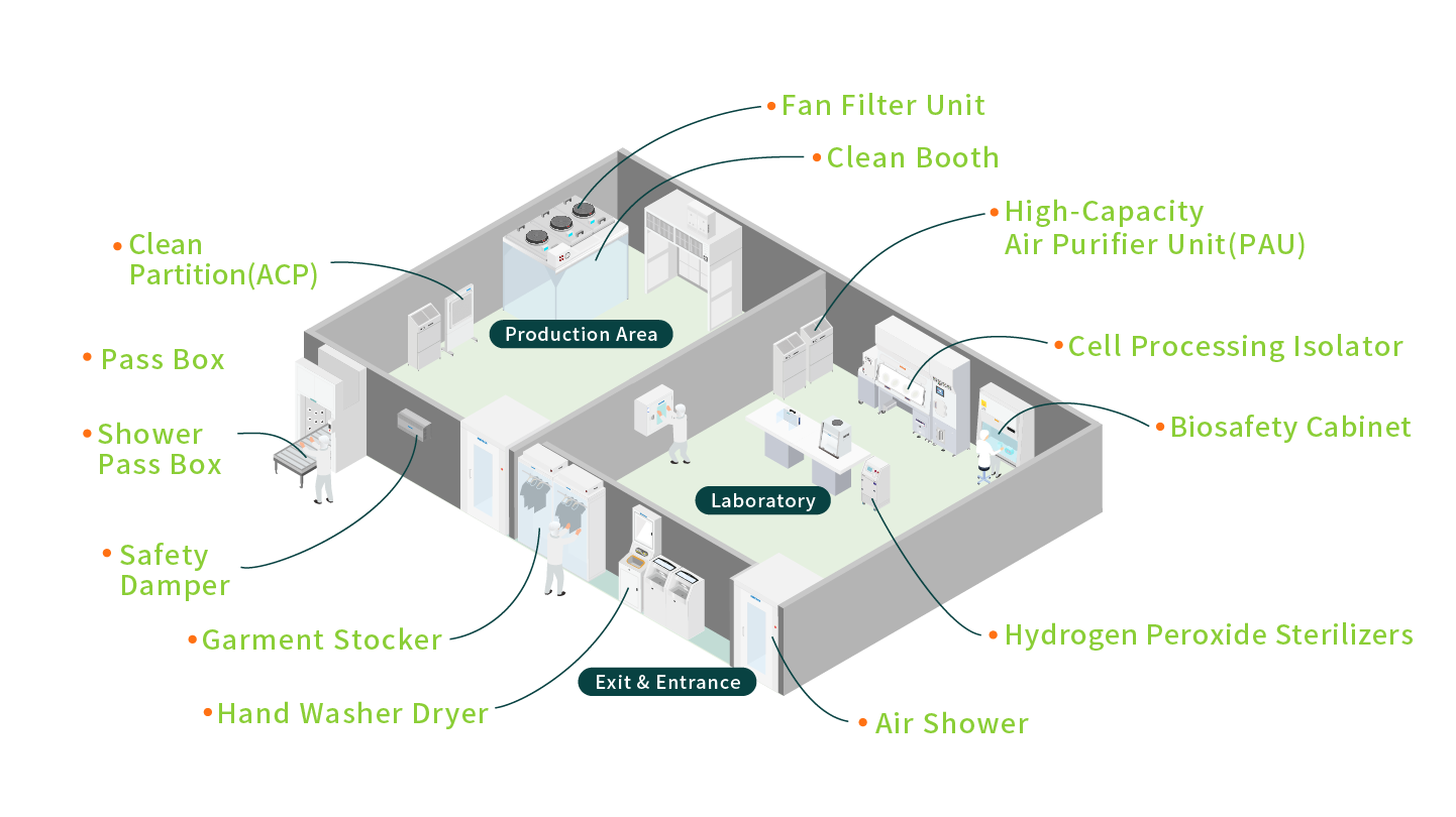
The production of pharmaceuticals and cosmetics must adhere to GMP standards, requiring a high level of cleanliness throughout every stage, from manufacturing to storage. To assist in controlling particulate and microbial contamination, we provide comprehensive solutions, including Biosafety Cabinets, Nexcell, Clean Booths, Laminar Flow Benchs, and Pass boxes.
Particularly in aseptic filling and cell culture processes, our equipment ensures compliance with regulatory requirements at every stage of production, achieving high stability and minimizing contamination risks. This enables the production of safer, higher-quality products.
- Biosafety Cabinet (Class ⅡB2)、Biosafety Cabinet (Class ⅡA2)- Designed for handling biohazardous materials, these cabinets are equipped with a negative pressure air filtration system to ensure containment and prevent leakage of hazardous substances.
- Nexcell- This cutting-edge equipment is the result of a collaborative effort by three leading Japanese companies—AIRTECH, WAKENYAKU CO.,LTD., and TOMY DIGITAL BIOLOGY CO., LTD. contributing expertise from their respective fields.
- Vertical Laminar Flow Bench (VS)- The Bench provides a localized clean and sterile working environment. It includes a controlled exhaust system to filter and safely discharge contaminated air from the workspace, protecting both operators and the environment. The Bench is an ideal solution for microbiological applications requiring safety and precision.
5.Hospitals
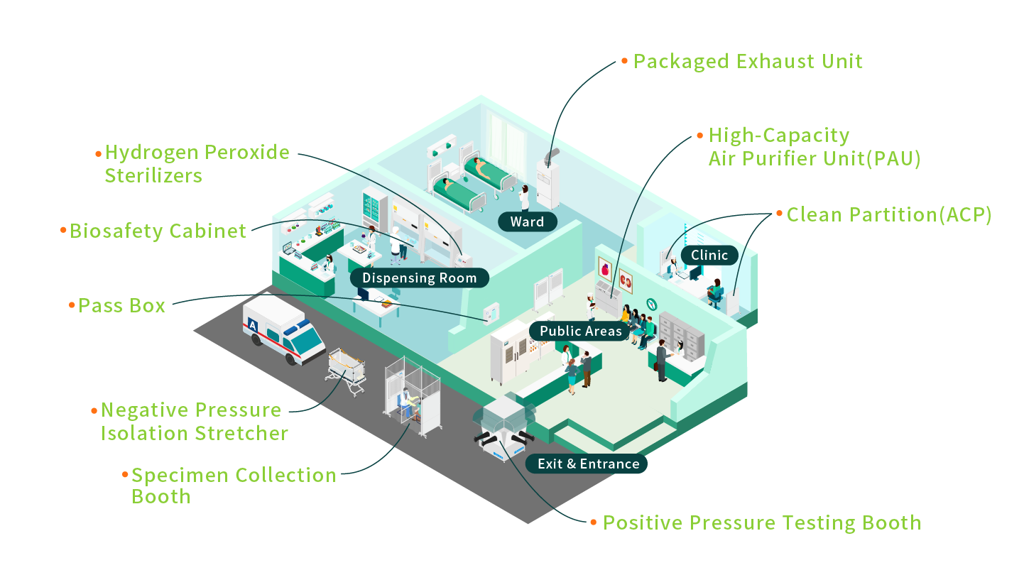
Operating rooms, laboratories, and isolation wards in hospitals must maintain a high level of cleanliness to prevent cross-contamination and the spread of pathogens. We provide advanced medical-grade cleanroom equipment, including Pass boxes, Negative Pressure Isolation Stretcher, Specimen Collection Booth, Positive pressure testing booth,Hydrogen Peroxide Sterilizers (Gas Generator) and Packaged exhaust unit, designed to create safe and reliable medical environments.
From sample transfer to air sterilization, our integrated solutions address diverse medical needs, ensuring patient safety, improving healthcare efficiency, and establishing contamination-free operations that meet international medical standards.
- Negative Pressure Isolation Stretcher(BS-Cap-Ⅲ)- The capsule maintains a negative pressure environment, isolating viruses and bacteria expelled by patients during coughing. This effectively prevents cross-infection by filtering contaminated air through high-efficiency HEPA filters and releasing purified air back into the environment.
- Packaged exhaust unit(PEU)- Designed for infection control, this unit prevents the spread of infectious diseases and ensures the safety of healthcare personnel and patients. Contaminated air is filtered through high-performance HEPA filters, with clean air discharged outdoors. It prevents cross-contamination between isolation zones and other areas, such as offices or rest zones, while maintaining a negative pressure environment.
Worldwide standard
Cleanliness
The cleanroom classification standards FS 209E and ISO 14644-1 require specific particle count measurements and calculations to classify the cleanliness level of a cleanroom or clean area.
ISO 14644-1
| Maximum concentration limits (particles/m3 ) | ||||||
|---|---|---|---|---|---|---|
| Classification Number (N) | 0.1μm | 0.2μm | 0.3μm | 0.5μm | 1.0μm | 5.0μm |
| ISO Class 1 | 10 | - | - | - | - | - |
| ISO Class 2 | 100 | 24 | 10 | - | - | - |
| ISO Class 3 | 1,000 | 237 | 102 | 35 | - | - |
| ISO Class 4 | 10,000 | 2,370 | 1,020 | 352 | 83 | - |
| ISO Class 5 | 100,000 | 23,700 | 10,200 | 3,520 | 832 | - |
| ISO Class 6 | 1,000,000 | 237,000 | 102,000 | 35,200 | 8,320 | 293 |
| ISO Class 7 | - | - | - | 352,000 | 83,200 | 2,930 |
| ISO Class 8 | - | - | - | 3,520,000 | 832,000 | 29,300 |
| ISO Class 9 | - | - | - | 35,200,000 | 8,320,000 | 293,000 |
Federal Standard 209E Airborne Particulate Cleanliness Classes
| CR Cleanliness | Diameter for Airborne Particle | ||||||||||
|---|---|---|---|---|---|---|---|---|---|---|---|
| 0.1μm | 0.2μm | 0.3μm | 0.5μm | 0.5μm | |||||||
| Volume Units | Volume Units | Volume Units | Volume Units | Volume Units | |||||||
| SI | Class | (m3) | (ft3) | (m3) | (ft3) | (m3) | (ft3) | (m3) | (ft3) | (m3) | (ft3) |
| M1 | 350 | 9.91 | 75.7 | 2.14 | 30.9 | 0.875 | 10.0 | 0.283 | - | - | |
| M1.5 | 1 | 1240 | 35.0 | 265 | 7.50 | 106 | 3.00 | 35.3 | 1.00 | - | - |
| M2 | 3,500 | 99.1 | 757 | 21.4 | 309 | 8.75 | 100 | 2.83 | - | - | |
| M2.5 | 10 | 12,400 | 350 | 2,650 | 75.0 | 1,060 | 30.0 | 353 | 10.0 | - | - |
| M3 | 35,000 | 991 | 7,570 | 214 | 3,090 | 87.5 | 1,000 | 28.3 | - | - | |
| M3.5 | 100 | - | - | 26,500 | 750 | 10.600 | 300 | 3,530 | 100 | - | - |
| M4 | - | - | 75,700 | 2,140 | 30,900 | 875 | 10,000 | 283 | - | - | |
| M4.5 | 1000 | - | - | - | - | - | - | 35,300 | 1,000 | 247 | 7.00 |
| M5 | - | - | - | - | - | - | 100,000 | 2,830 | 618 | 17.5 | |
| M5.5 | 10,000 | - | - | - | - | - | - | 353,000 | 10,000 | 2,470 | 70.0 |
| M6 | - | - | - | - | - | - | 1,000,000 | 28,300 | 6,180 | 175 | |
| M6.5 | 100,000 | - | - | - | - | - | - | 3,530,000 | 100,00 | 24,700 | 700 |
| M7 | - | - | - | - | - | - | 10,000,000 | 283,000 | 61,800 | 1,750 | |
JIS B 9920
| Class | Maximum concentration limits (particles/m3 ) | |||||
|---|---|---|---|---|---|---|
| 0.1μm | 0.2μm | 0.3μm | 0.5μm | 1μm | 05μm | |
| Class1 | 10 | 2 | - | - | - | - |
| Class2 | 100 | 24 | 10 | 4 | - | - |
| Class3 | 100 | 237 | 102 | 35 | 8 | - |
| Class4 | 10,000 | 2,370 | 1,020 | 352 | 83 | - |
| Class5 | 100,000 | 23,700 | 10,200 | 3,520 | 832 | 29 |
| Class6 | - | 237,000 | 102,000 | 35,200 | 8,320 | 293 |
| Class7 | - | - | - | 352,000 | 83,200 | 2,930 |
| Class8 | - | - | - | 3,520,000 | 832,000 | 29,300 |
| Class9 | - | - | - | 35,200,000 | 8,320,000 | 293,000 |
Britain BS 5295
| Classs | Maximum concentration limits (particles/m3 ) | |||||||
|---|---|---|---|---|---|---|---|---|
| 0.5μm | 1.0μm | 5.0μm | 10μm | 25μm | ||||
| Class 1 | 3,000 | - | 0 | 0 | 0 | |||
| Class 2 | 300,000 | - | 2,000 | 30 | - | |||
| Class 3 | - | 1,000,000 | 20,000 | 4,000 | 300 | |||
| Class 4 | - | - | 200,000 | 40,000 | 4,000 | |||
Worldwide Standard comparison
| Worldwide Standard | Class | |||||
|---|---|---|---|---|---|---|
| ISO 14644-1 | ISO 3 | ISO 4 | ISO 5 | ISO 6 | ISO 7 | ISO 8 |
| FS 209E | Class 1 | Class 10 | Class 100 | Class 1000 | Class 10000 | Class 100000 |
| FS 209E(SI) | M1.5 | M2.5 | M3.5 | M4.5 | M5.5 | M6.5 |
| JIS B 9920 | Class 3 | Class 4 | Class 5 | Class 6 | Class 7 | Class 8 |
| Britain BS 5295 | C | D | E/F | G/H | J | K |
| Germany VD I.2083 | 1C | 2 | 3 | 4 | 5 | 6 |
| Australia AS 1386 | 0.035 | 0.35 | 3.5 | 35 | 350 | 3500 |
| France AFNOR X44101 | - | - | 4,000 | - | 4,000 | 4,000,000 |
| Grade | - | A/B | - | C | ||
PIC/S GMP Guide
For the manufacture of sterile medicinal products
The “in operation” and “at rest” states should be defined for each clean room or suite of clean rooms. For the manufacture of sterile medicinal products 4 grades can be distinguished:
| Description | |
|---|---|
| Grade A | The local zone for high risk operations, e.g. filling zone, stopper bowls, open ampoules and vials, making aseptic connections. Normally such conditions are provided by a laminar air flow work station. Laminar air flow systems should provide a homogeneous air speed in a range of 0.36 – 0.54 m/s (guidance value) at the working position in open clean room applications. The maintenance of laminarity should be demonstrated and validated. A uni-directional air flow and lower velocities may be used in closed isolators and glove boxes. |
| Grade B | For aseptic preparation and filling, this is the background environment for the grade A zone. |
| Grade C | Clean areas for carrying out less critical stages in the manufacture of sterile products |
Clean rooms and clean air devices should be classified in accordance with EN ISO 14644-1. Classification should be clearly differentiated from operational process environmental monitoring. The maximum permitted airborne particle concentration for each grade is given in the following table:
| Maximum permitted number of particles/m3 equal to or greater than the tabulated size | ||||
|---|---|---|---|---|
| At rest | In operation | |||
| Grade | 0.5μm | 5μm | 0.5μm | 5μm |
| A | 3,500 | 0 | 3,500 | 0 |
| B | 3,500 | 0 | 3,500 | 2,000 |
| C | 350,000 | 2,000 | 350,000 | 20,000 |
| D | 3,500,000 | 20,000 | not defined | not defined |
- For classification purposes in Grade A zones, a minimum sample volume of 1m³ should be taken per sample location.
- For Grade A the airborne particle classification is ISO 4.8 dictated by the limit for particles ≥5.0 μm.
- For Grade B (at rest) the airborne particle classification is ISO 5 for both considered particle sizes.
- For Grade C (at rest & in operation) the airborne particle classification is ISO 7 and ISO 8 respectively.
- For Grade D (at rest) the airborne particle classification is ISO 8.
- For classification purposes EN/ISO 14644-1 methodology defines both the minimum number of sample locations and the sample size based on the class limit of the largest considered particle size and the method of evaluation of the data collected.
Examples of operations to be carried out in the various grades are given in the table below :
| Grade | Examples of operations for terminally sterilised products |
|---|---|
| A | Filling of products, when unusually at risk |
| B | Preparation of solutions, when unusually at risk. Filling of products |
| D | Preparation of solutions and components for subsequent filling |
| Grade | Examples of operations for aseptic preparations |
|---|---|
| A | Aseptic preparation and filling |
| B | Preparation of solutions to be filtered |
| D | Handling of components after washing |
HEPA Information
EN 1822:2009
| Filter Class | Overall Value | Local Value | ||||
|---|---|---|---|---|---|---|
| Efficiency(%) | Penetration(%) | Efficiency(%) | Penetration(%) | |||
| E10 | ≧85 | ≦15 | - | - | ||
| E11 | ≧95 | ≦5 | - | - | ||
| E12 | ≧99.5 | ≦0.5 | - | - | ||
| H13 | ≧99.95 | ≦0.05 | ≧99.75 | ≦0.25 | ||
| H14 | ≧99.995 | ≦0.005 | ≧99.975 | ≦0.025 | ||
| U15 | ≧99.9995 | ≦0.0005 | ≧99.9975 | ≦0.0025 | ||
| U16 | ≧99.99995 | ≦0.00005 | ≧99.99975 | ≦0.00025 | ||
| U17 | ≧99.999995 | ≦0.000005 | ≧99.9999 | ≦0.001 | ||
- EPA 10 - EPA 12: Efficiency Particulate Air Filters
- HEPA 13 - HEPA 14: High Efficiency Particulate Air Filters
- ULPA 15 - ULPA 17: Ultra Low Penetration Air Filters
DIN EN 779:2012
| Group | Class | Final pressure drop (Pa) | Average arrestance (%) | Average efficiency (%) | Minimum efficiency @0.4µm (%) |
|---|---|---|---|---|---|
| Coarse dust filter | G1 | 250 | 50 ≤Am< 65 | - | - |
| G2 | 250 | 65 ≤ Am< 80 | - | - | |
| G3 | 250 | 80 ≤ Am< 90 | - | - | |
| G4 | 250 | 90 ≤ Am | - | - | |
| Medium | M5 | 450 | - | 40 ≤ Em< 60 | - |
| M6 | 450 | - | 60 ≤ Em< 80 | - | |
| Fine dust filter | F7 | 450 | - | 80 ≤ Em< 90 | 35 |
| F8 | 450 | - | 90 ≤ Em< 95 | 55 | |
| F9 | 450 | - | 95 ≤ Em | 70 |
ISO 29463:2011
| Filter Class | Overall Value | Local Value | ||||
|---|---|---|---|---|---|---|
| Efficiency(%) | Penetration(%) | Efficiency(%) | Penetration(%) | |||
| ISO 15 E | ≧95 | ≦5 | - | -- | ||
| ISO 20 E | ≧99 | ≦1 | - | -- | ||
| ISO 25 E | ≧99.5 | ≦0.5 | - | -- | ||
| ISO 30 E | ≧99.90 | ≦0.1 | - | -- | ||
| ISO 35 H | ≧99.95 | ≦0.05 | ≧99.75 | ≦0.25 | ||
| ISO 40 Hd | ≧99.99 | ≦0.01 | ≧99.95 | ≦0.05 | ||
| ISO 45 Hd | ≧99.995 | ≦0.005 | ≧99.975 | ≦0.025 | ||
| ISO 50 U | ≧99.999 | ≦0.001 | ≧99.995 | ≦0.005 | ||
| ISO 55 U | ≧99.999 5 | ≦0.000 5 | ≧99.997 5 | ≦0.002 5 | ||
| ISO 60 U | ≧99.999 9 | ≦0.000 1 | ≧99.999 5 | ≦0.000 5 | ||
| ISO 65 U | ≧99.999 95 | ≦0.000 05 | ≧99.999 75 | ≦0.000 25 | ||
| ISO 70 U | ≧99.999 99 | ≦0.000 01 | ≧99.999 9 | ≦0.000 1 | ||
| ISO 75 U | ≧99.999 995 | ≦0.000 005 | ≧99.999 9 | ≦0.000 1 | ||
Please note: These charts provide approximate data regarding various filter classes for reference purposes only. Specific data applicable to an intended application must be determined at the expected face velocity.
Filter Integrity Test
PAO Method
(For testing HEPA) In the PAO test, a gas type of smoke will be generated by the PAO generator. After using the photometer to test the concentration on the upstream of the HEPA, a particle counter will be put at the air exhaust area to test the PAO concentration that passes through HEPA. The distance between the particle counter and HEPA will be around 25mm with testing speed at 50mm/sec. The test range includes HEPA filter and its connecting area. However, there are no related guidelines on the measurement method. Just make sure the whole HEPA covered area are tested for leakage. If there are particles over 0.03 are tested, hold the particle counter for 10 sec and then test.
back and forth at the range of 100mm. Once the particles are less than 0.03, proceed the test.PAO efficiency (%) = ( 1-particle concentration at the HEPA air exhaust area / particle concentration at the HEPA upstream area ) × 100%.
Colorimetry
(For testing Medium Filter or Bag Filter) This is to test the integrity of the Medium Filter mainly for particle size ≧1μm. There will be the same filter indicator paper at the up/downstream of the filter. After sampling, we calculate the filter integrity based on its transparency variation. Normally the NBS method and ASHRAE method ( 52.1 —92 Standard ) are applied. In 1968年, after modification and consolidation, it is called ASHRAE Efficiency or NBS. Both represent Colorimetry.
Q1:The sampling air volume through the upstream indicator paper.
Q2:The sampling air volume through the downstream indicator paper.
O1:The opacity of the upstream indicator paper with particles on it.
O2:The opacity of the downstream indicator paper with particles on it.
Colorimetry efficiency (%)=( 1- Q1/Q2×Q2/Q1)×100%
Arrestance
(For testing pre-filter) This is to test the efficiency of the pre-filter on larger particles which sizes are ≧5μm.
Normally AFI method (in 1960) and ASHRAE method (52.1—92 Standard) are applied.
It is called ASHRAE Arrestance or AFI. Both represent Arrestance.
Wf:The particle quantity supplied at the upstream of the filter(g)
Wp:The weight of the particles attached on the filter(g)
Arrestance efficiency (%)=( 1- Wp/Wf)×100%
When to conduct Leak test?
- HEPA replacement
- Machine re-installation
- Regular test (at least once a year)
After-sales service
| Professional Technique | AIRTECH customer service engineers are all authorized by AIRTECH Japan. We conform to the International Inspection Procedures to make sure we offer the best technique and support. |
|
|---|---|---|
| Strick control | All the test equipment is under regular maintenance and calibration to make sure our quality conforms with International standard. |
|
| Main Products |
|
|
| Test Items |
|
|
| Immediate support | We have enough stock to make sure we can deliver the spare parts within the short period of time. |
|
| Warranty | 1.One year after we ship out. 2.If below conditions occur, there will be certain cost.
|
|
Remark 1: Testing items will vary from product type.
Remark 2: The warranty items are only applied in Taiwan.

